Our previous article, Retaining Wall: A Design Approach discusses the principle and concept behind and when and where to consider a retaining wall in our design. We have learned the different checks against the mode of failures in the retaining wall should be considered in the design. To further understand the designed approach, here is a worked example of the design of the retaining wall.
This example is intended to be readily calculated by hand although a lot of structural spreadsheets and software such as Prokon are available. The purpose of this article is for the reader to fully understand the principle behind it.
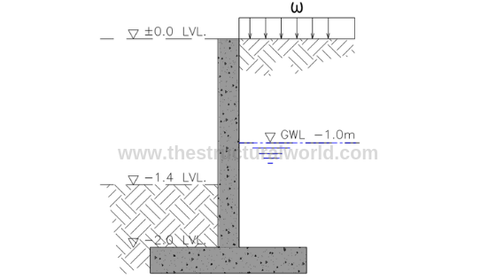
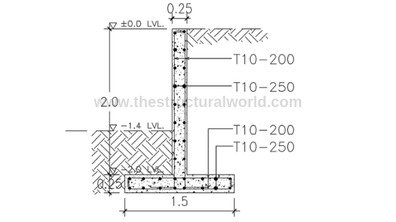
Figure A.1-Retaining Wall Cross Section
Consider the cantilever retaining wall with the cross-section shown in the above Figure A.1, which retains a 2m depth of soil having the groundwater table at -1.0m level.
1. Analytical Geometry and Variables
Before we proceed with the design, it is important for the designer to know the geometric variable and parameters of the retaining wall. Refer to Figure A.2 below.
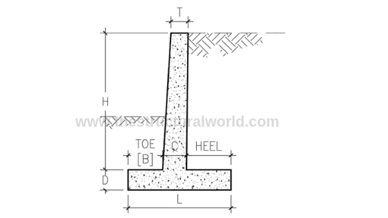
Figure A.2-Retaining Wall Geometric Variables
The next thing to consider is the assumptions that we can make in terms of the geometry of the retaining wall that we are designing. Given the height, H of the retaining wall, we can assume or counter check our initial design considerations should at least according to the following geometric proportions:
Based on the above approximate geometric proportions, let us assumed the following parameters to be used in our design:
Sketches of the retaining wall forces should be considered to properly distinguish the different forces acting on our retaining wall as tackled in the previous article, Retaining Wall: A Design Approach. Based on our example in Figure A.1, we have the forces due to soil pressure, due to water and surcharge load to consider. Figure A.3 below is most likely our analytical model.
READ ALSO: Personal Protective Equipment (PPE) in Construction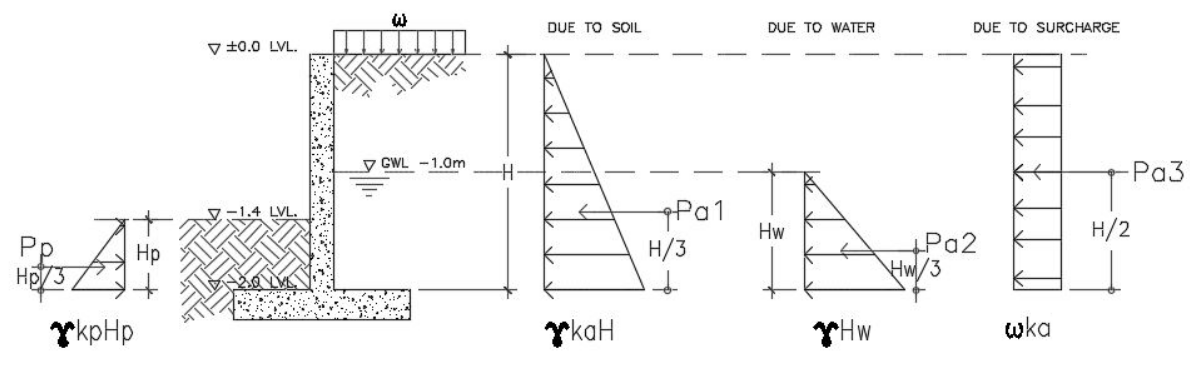
Figure A.3-Retaining Wall Forces Diagram
Considering the Figure A.3, we can derive the following equation for the active pressures, Pa and passive pressure Pp. Notice that the pressures acting on the wall are equivalent to the area (triangle) of the pressure distribution diagram. Hence,
The passive pressure, Pp would be:
According to Rankine and Coulomb Formula, the following are the equation in calculating the coefficient of pressure:
Ka= (1-sin ф)/(1+sin ф)
Kp= (1+sin ф)/(1-sin ф)
Substituting the values, we have the following results:
There are two checks to consider the stability of the retaining wall. One is the check for an overturning moment and the other one is the check for sliding. The weight of the retaining wall including the gravity loads within it plays a vital role in performing the stability check. Refer to Figure A.4 for the mass or weight calculations.
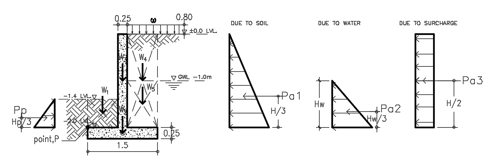
Figure A.4-Retaining Wall Weight Components
The self-weight component of the retaining wall should be factored down or to be multiplied by weight reduction factor (0.9) to account for uncertainty because they are “stabilizing” in this context. Hence,
To satisfy the Overturning Moment Stability, the following equation should follow:
With reference to Figure A.4 diagram and taking moment at the point, P conservatively neglecting the effect of passive pressure hence:
RM/OM = 5.32 > 2.0, hence SAFE in Overturning Moment!
To satisfy the stability against sliding, the following equation should govern:
The sliding check should be carried out with reference to the Figure A.4 diagram and considering the summation of vertical forces for resisting force and horizontal forces for sliding force conservatively neglecting the passive pressure, hence:
RF/SF = 2.79 > 1.5, hence SAFE for Sliding!
The nominal shear is equal to the lateral forces on the retaining wall, neglecting the effect of passive pressure which will give us:
For the thickness of the wall to be safe in shear, the ultimate shear, Vu should less than the allowable shear, Vallow as recommended by the ACI 318 code.
d= 250mm-75mm-6mm = 169mm
Vallow= 121.89kN
Since Vu < Vallow, hence SAFE in Shear!
Mu =φ fc’ bd 2 ω (1- 0.59 ω)
17.40×10 6 = 0.90 x 32 x 1000 x 169 2 ω (1-0.59 ω)
ρ = ω fc’/fy= 0.00150
As= ρbd = 0.00150x1000x169 = 254mm 2
Asmin= ρminbt = 0.002 x 1000 x 250 = 500mm 2
Required Vertical Bar: Try T10-200; As act= 392mm 2 x 2 sides = 785.4mm 2
Required Horizontal Bar: Try T10-250; As act= 314mm 2 x 2 sides= 628.32mm 2
Hence: use T10-200 for vertical bar and T10-250 for horizontal bar.
The foundation bearing capacity usually governs the design of the wall. The soil, particularly under the toe of the foundation, is working very hard to resist the vertical bearing loads, sliding shear, and to provide passive resistance to sliding. The bearing capacity of the soil should be calculated taking into account the effect of simultaneous horizontal loads applied to the foundation from the soil pressure.
For the footing to be safe in soil pressure, the maximum soil pressure under working load shall be less than the allowable soil bearing capacity. The maximum soil bearing pressure under the footing considering 1m strip is:
Substituting the values above will give us:
qmax= 70.81kPa < qall=100 kPa, hence, oK!
Solving for Ultimate bearing pressure:
Substituting the values above will give us:
If qumin is in tension check the required length otherwise ignore if it is in compression. Since our qumin is tension (+), the value of L must be computed as follows:
READ ALSO: Hydrostatic Uplift Check in Basements & Substructures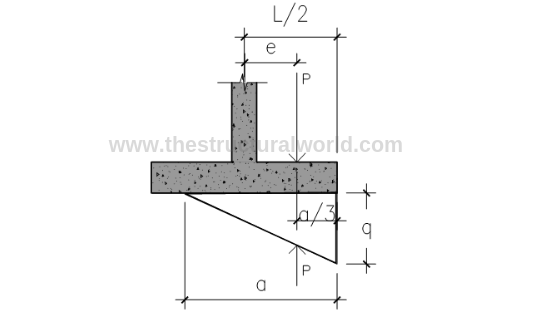
Figure A.5-Pressure Diagram under Tension
Solve for Eccentricity:
e=M/P = 0.181
L= 2(e+a/3) = 1.52 say 1.6m
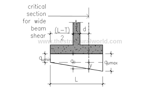
Fig A.6-Pressure Diagram under Compression
Solving for y by similar triangle: referring to Figure A.6 above
y/1.044 = (112.24-19.44)/1.5; y = 64.59 kPa
qc= 19.44 + 64.59 = 84.03 kPa
Vu= 44.75kN
Solving for y by similar triangle: (referring to Figure A.6 above, L=a=1.75)
y/1.244= 112.24/1.75; y = 79.79 kPa
qc=79.79kPa
Vu=34.18kN
Hence, use: Vu=44.75kN
Vallow= 121.89kN
Since Vu < Vallow, hence SAFE in Shear!
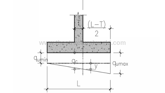
Figure A.7-Pressure Diagram for Flexure Check
Solving for y by similar triangle:(referring to Figure A.7 above)
y/0.875 = (112.24-19.44)/1.5; y = 54.13 kPa
qc= 19.44 + 54.13 = 73.57 kPa
Mu= (73.57×0.625) x (0.625/2) + (38.67×0.625) (1/2) x (2/3) (0.625) → (area of trapezoid x lever arm)
Mu=19.40 kNm
Solving for y by similar triangle: (referring to Figure A.7 above. L=a=1.75)
y/1.075 = 112.24/1.75; y = 68.95 kPa
qc=19.44 + 68.95= 88.39 kPa
Mu = (88.39×0.75) x (0.75/2) + (23.85×0.75) (1/2) x (2/3) (0.75) → (area of trapezoid x lever arm)
Hence, use Mu=29.33kNm
Mu =φ fc’ bd 2 ω (1- 0.59 ω)
29.33×10 6 = 0.90 x 32 x 1000 x 169 2 ω (1-0.59 ω)
ρ = ω fc/fy= 0.002532
As= ρbd = 0.002532x1000x169 = 428mm 2
Asmin= ρminbt = 0.002 x 1000 x 250 = 500mm 2
Required Vertical Bar: Try T10-200; As act= 392mm 2 x 2 sides = 785.4mm 2
Required Horizontal Bar: Try T10-250; As act= 392mm 2 x 2 sides= 628.32mm 2
The presented calculations above are actually too tiring to perform manually especially if you are doing a trial and error design. Thanks to structural design soft wares and spreadsheets, available nowadays, our design life will be easier.
Our team developed a user-friendly spreadsheet for the design of cantilever retaining wall based on the above calculation. Grab your copy here!
What do you think about this article? Tell us your thoughts! Leave a comment on the section below. Subscribe to our newsletter to be updated with the latest posts or follow us on our social media pages on the below icons.